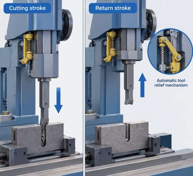
A vertical slotter cuts on the downward stroke. During the return stroke, the tool should move slightly away from the workpiece.
Without this relief movement, the tool flank can rub against the finished surface while the ram travels upward. The result is fast tool wear, scratches inside the bore and a rough keyway or slot.
An automatic tool relief mechanism keeps the tool locked for cutting and slightly lifted for return. It may use a mechanical cam, linkage or hydraulic system. The movement is small, but its effect on tool life and surface finish is large.
Why the Return Stroke Causes Scratches and Tool Wear
A slotting tool removes metal as the ram moves down. The cutting edge takes the load, produces a chip and finishes one part of the slot wall. The ram then travels back up to start the next stroke.
If the tool stays fixed in the cutting position, its rear face can drag across the newly machined surface. This contact may be small, but it repeats on every stroke. On a deep internal keyway, the tool can rub thousands of times during one job.
Operators usually notice fine vertical scratches inside the bore, a dull tool edge after a short cutting time, heat or rubbing noise during the return stroke, and a surface that becomes worse as the slot gets deeper.
Increasing coolant may reduce heat, but it cannot replace tool relief. The tool must leave the wall during the non-cutting stroke.
How Automatic Tool Relief Works
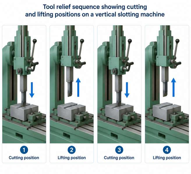
The basic sequence is simple:
- The tool holder moves down into the cut.
- The relief mechanism holds the tool in the cutting position.
- The cutting edge removes material on the downstroke.
- At the bottom or reversal point, the mechanism releases the tool slightly.
- The tool lifts away from the wall during the upstroke.
- Before the next cut, the tool returns to its set position.
The lift is normally small. Too little movement leaves rubbing. Too much movement can cause impact, lost position or an uneven cut when the tool returns.
The mechanism must work in time with the ram movement and remain repeatable at different stroke speeds.
Mechanical and Hydraulic Tool Relief Compared
| Relief type | How it works | Main strength | Point to check |
|---|---|---|---|
| Mechanical cam or linkage | Ram movement operates a fixed lifting path | Simple and repeatable | Cam wear and adjustment |
| Spring-loaded holder | Spring provides limited return clearance | Compact and easy to service | Spring force and return position |
| Hydraulic relief | Cylinder lifts the tool at the set point | Adjustable for heavier tools | Pressure, seals and timing |
| No automatic relief | Tool stays in cutting position | Lower initial cost | Rapid wear and surface rubbing |
A mechanical system has a direct connection to ram movement. A hydraulic system can offer more adjustment, but its pressure and timing must remain stable.
The key question is whether the tool clears the workpiece on every return stroke without changing the cutting position.
Vertical Slotter Tool Relief Troubleshooting
| Symptom | Likely cause | First check |
|---|---|---|
| Scratches on the return side | Relief is missing or too small | Observe tool clearance on upstroke |
| Tool edge wears quickly | Flank rubbing or poor lubrication | Check relief and tool geometry |
| Tool hits the workpiece | Relief is too large or mistimed | Inspect timing and stops |
| Slot width changes | Tool does not return consistently | Check holder play and adjustment |
| Rough finish at depth | Deflection or chip packing | Reduce overhang and clear chips |
| Relief changes with speed | Hydraulic delay or worn parts | Test at several ram speeds |
| Noise at reversal | Loose linkage or hard impact | Check pins, springs and stops |
What the Operator Should Check
Remove chips and inspect the tool holder, relief linkage and contact points. Look for worn pins, loose bolts, damaged springs or oil leakage around a hydraulic cylinder.
Then run the ram at a slow, safe speed and observe the tool during the return stroke. The tool should clear the wall without striking it. Follow the machine lockout procedure before making adjustments, and never place hands inside the work area.
Tool overhang also matters. A long bar can bend during cutting and touch the wall during return, even when the relief mechanism is working correctly. Use the shortest practical bar and keep the cutting edge sharp.
For internal keyways and vertical slotting work, review the MFG Machinery slotting machine range to compare stroke length, tool-holder design and automatic relief arrangements: MFG Machinery Slotting machine range.
Why Tool Relief Affects Surface Finish
Without relief, the return stroke can damage the surface that was just cut. The operator may then need to reduce the feed, use lighter cuts or perform extra finishing work.
With stable relief, the cutting edge works mainly on the downstroke. This helps the tool keep a sharper edge and gives the bore or keyway a more even finish.
The benefit is especially clear on deep internal keyways, blind slots, hard materials, long production runs and close-clearance mating parts.
A relief mechanism does not correct a dull tool, poor alignment or excessive tool-bar overhang. It removes one repeated source of damage: contact during the non-cutting stroke.
Cut on the way down. Clear the wall on the way up.
Market Insight: Buyers Are Checking the Return Stroke
Slotting-machine buyers often compare ram stroke, table size and cutting force. For internal work, they are also asking how the tool behaves between cuts.
A machine that cuts strongly but rubs on every return can consume tools quickly and leave scratches that are difficult to remove. Buyers are therefore checking relief travel, adjustment range, timing and access to wear parts.
This small mechanism has a direct effect on daily production. It can decide whether a keyway is ready for assembly or needs another finishing operation.
Send the Application Details
For a slotting-machine recommendation, send the workpiece material, bore diameter, keyway width and depth, slot length, tool-bar size and required surface finish.
Also include the expected production quantity and a photo showing the current scratches or worn tool edge. These details help MFG Machinery review the required stroke, tool relief arrangement and working capacity.
Send the information to info@mfg-machinery.com with the subject:
Vertical Slotter Application – Bore Size / Keyway Size / Material