A C-frame press provides open access from three sides, but its open throat can flex slightly under load. As the force rises, the upper and lower working surfaces may no longer remain perfectly parallel. This elastic movement is often called the “yawning” effect.
Common signs include a heavy burr on one side of the part, uneven die wear and a shut height that changes from front to back.
- The main controls are straightforward:
- Keep the load close to the press centerline.
- Avoid running near full capacity on every cycle.
- Use a properly guided die set.
- Check parallelism under load, not only when the press is idle.
- Review frame-deflection data for the actual load position.
The Press Looks Square Until the Load Arrives
During setup, the ram and bolster may measure parallel. The die closes smoothly by hand, and the first light test produces a good part. The problem often appears only when production force approaches the upper range of the press.
Under load, the open side of the frame stretches slightly while the rear section carries the reaction force. This causes the throat to open by a small amount. Once the pressure is released, the frame normally returns to its original position.
The movement may be elastic, but the tooling feels it during every cycle. A small change may have little effect on a general assembly job. On precision punching or forming work, however, it can shift the load to one side of the die and change the cutting clearance.
What the Workpiece Is Telling You
A finished part often shows the fault before any movement can be seen on the machine.
| Production symptom | Possible cause | First check |
|---|---|---|
| Heavy burr on one side | Die gap changes under load | Loaded parallelism |
| One-sided punch wear | Uneven or offset load | Tool position |
| Part thickness varies | Ram and bolster tilt | Frame deflection |
| Die guides become hot | Guides carry side force | Tool alignment |
| Light test parts are good | Deflection rises with force | Production-load test |
| Fault changes after die movement | Load position affects frame | Center of load |
Uneven burrs can also come from a worn punch, incorrect die clearance or loose tooling. Check these items before treating the press frame as the cause.
Load sensitivity is a useful clue. If the fault becomes more serious as pressure rises, frame or tooling deflection is more likely.
Why Center of Load Matters
The rated tonnage normally assumes that force is applied within the intended working area. It does not mean full force can be placed anywhere on the bolster.
When a small die sits too close to the open front of a C-frame press, the force creates extra leverage on the throat. The same tonnage can then produce more angular movement than a centered load.
Keep the tool’s center of load as close as possible to the press centerline. Remember that the geometric center of the die is not always the true load center. An uneven part shape, different punch lengths or an offset forming area can move the actual force toward one side.
Before production, identify where the material first contacts the tool and where the highest force occurs.
What FEA Should Show in a Press Frame
Finite element analysis, or FEA, helps engineers predict how a press frame will respond before the steel is cut and welded.
For a C-frame press, the analysis should show more than whether the frame can withstand maximum stress. It should also review throat opening, angular change between the ram and bolster, and stress around the inner corners of the frame.
The test conditions matter. Results should cover the normal production force, maximum planned load and permitted offset-load positions.
Color plots are easy to display, but the useful result is the expected movement at the die area. Two frames may both remain below the steel’s strength limit while showing very different levels of working deflection.
FEA is only as reliable as its inputs. Cylinder position, bolster support, weld structure, contact points and load area must match the real press.
When selecting a machine for an automated or close-tolerance process, buyers can use the available C-frame hydraulic press configurations from MFG Machinery to compare throat depth, table size and working capacity against the actual die layout.
Can a Guided Die Set Solve the Problem?
A die set with guide posts and bushings helps the upper and lower tools stay aligned. It is useful for close-clearance punching and other work where lateral movement can damage the cutting edges.
However, the guide posts should guide the tool. They should not be expected to force a heavily tilted press back into position.
If frame deflection is excessive, the guide system may carry repeated side loads. This can cause hot bushings, scoring, guide-post wear and early die failure.
A reliable setup combines four elements:
Rigid frame + centered load + suitable press capacity + guided tooling
A guided die set improves tool alignment, but it cannot correct a press that is too small or poorly matched to the job.
A Simple Loaded-Parallelism Check
Begin with the machine safely isolated. Inspect the ram, bolster, die-mounting surfaces and fasteners. Remove dirt, scale and damaged packing before taking measurements.
A trained technician can place dial indicators at suitable points and apply force through an approved test block or fixture. Readings should be recorded at low load, normal working load and the highest planned production load.
If the angular change rises sharply near the top of the range, the process may be operating too close to the machine’s practical limit.
Never place hands or measuring equipment inside an unsupported press working area. All testing must follow the machine maker’s blocking and safety procedure.
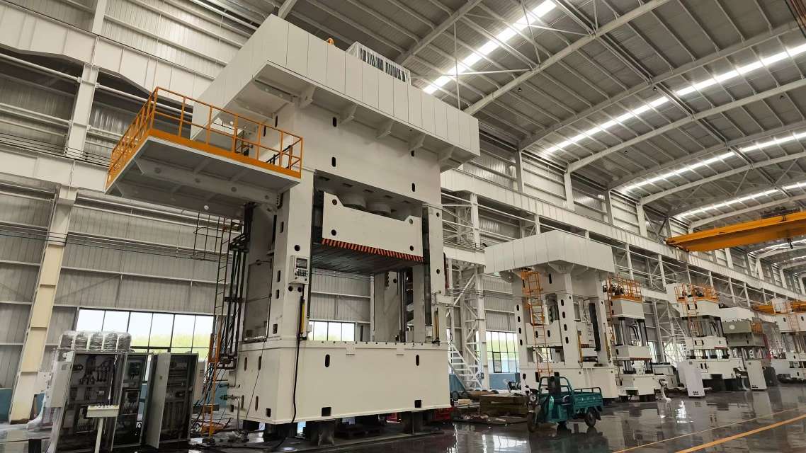
Market Insight: Buyers Are Asking for Deflection Data
Press buyers used to focus mainly on maximum tonnage, stroke and table size. Precision assembly and punching lines now require more detail.
A machine may produce its rated force and still be unsuitable for a close-clearance die. Buyers are therefore asking about loaded parallelism, permitted offset force, throat deflection and the location of the rated working area.
This is especially important on automated lines. A robot repeats the same loading position, but it also repeats the same alignment error. Small die wear can become a batch-wide problem before an operator notices it.
Send the Real Load Case
For a useful C-frame press review, send MFG Machinery the required working force, die dimensions, load position and expected off-center distance. Include the part material, process type, stroke, shut height, cycle rate and required part tolerance.
A die-layout drawing should show the punch positions and expected center of load. Photos of one-sided burrs or uneven tool wear can also help determine whether the problem comes from the press, tooling or setup.
Send the application details to info@mfg-machinery.com with the subject:
C-Frame Press Review – [Working Force] / [Die Size] / [Load Position]