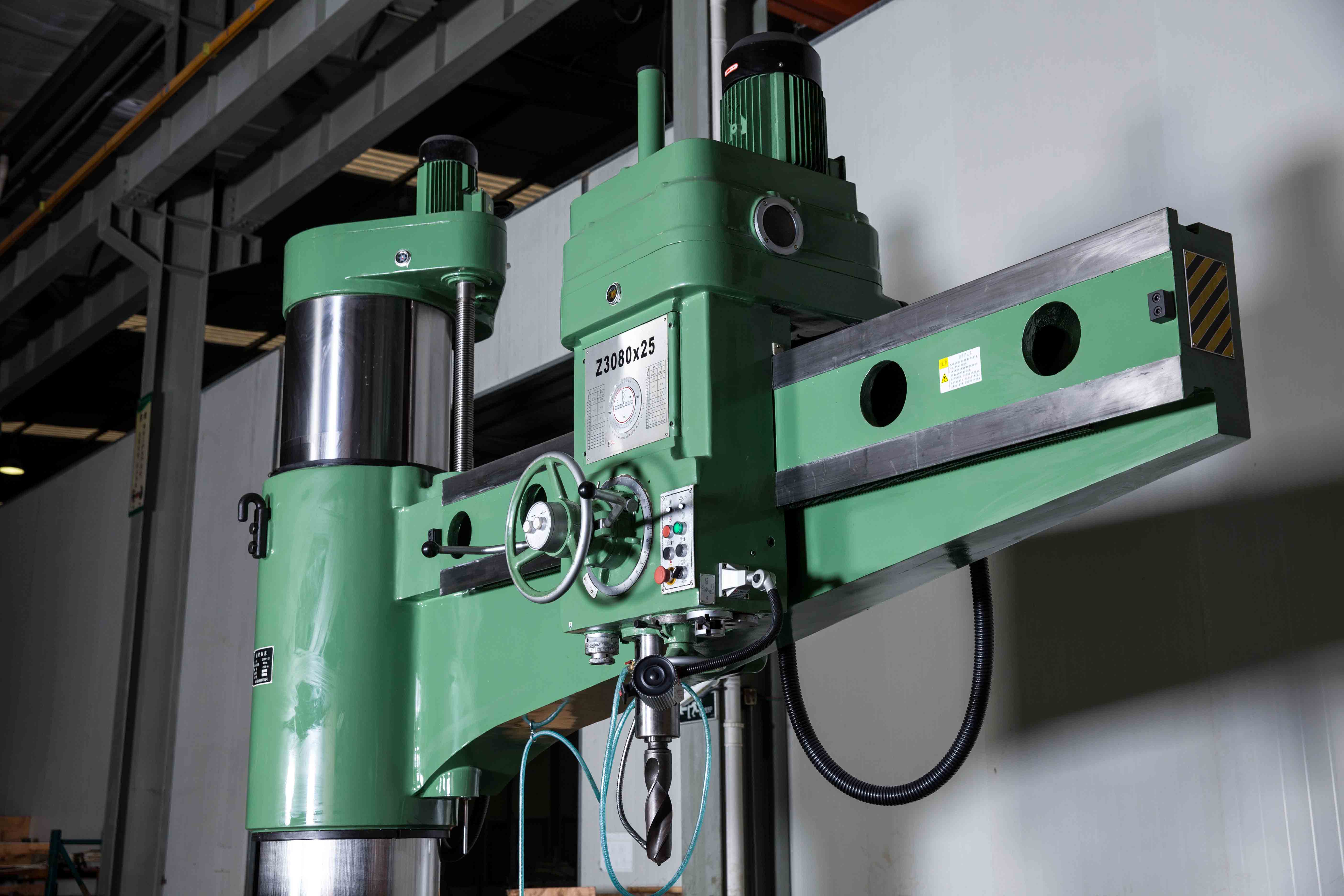
Radial drilling machines are essential workhorses in modern industrial manufacturing. However, prolonged operation under heavy loads can lead to standard wear and tear. To help operators and maintenance engineers minimize downtime, this comprehensive troubleshooting guide details the most common after-sales issues, their root causes, and professional solutions.
I.Quick Reference:High-Frequency Faults in Hydraulic Radial Drilling Machines (3040 / 3050 / 3080 Series)
| Component Group | Common Symptoms | Primary Root Cause | Recommended Action |
| Hydraulic Arm | Arm fails to lift, moves slowly, or stutters | Low oil level, degraded fluid, or worn piston seals | Replenish/change hydraulic oil; replace seals |
| Clamping Mechanism | Radial arm or spindle box slips during heavy cutting | Internal leakage in clamping cylinder; worn gibs | Replace oil seals; adjust or regrind guide rail gibs |
| Spindle Drive | Spindle won't rotate or slips at high speed | Motor phase loss; worn friction plates; stretched V-belt | Repair motor; replace friction plates; adjust/replace belt |
| Precision & Quality | Hole deviation; excessive runout; rough surface finish | Worn spindle bearings; damaged Morse taper; loose anchor bolts | Replace bearings; regrind Morse taper; re-level machine |
| Electrical System | Machine won't start; solenoid valves fail to engage | Tripped circuit breaker; burnt coil; failed limit switch | Reset breaker; replace solenoid coil or limit switch |
| Coolant & Lubrication | Low coolant flow; dry guide rails | Damaged impeller; clogged filter; failed lubrication pump | Clean filter; replace pump impeller or lubrication pump |
II. Exclusive Issues for Mechanical Manual Radial Drills (Traditional Z3032/Z3040 Models)
Unlike hydraulic models, manual radial drills rely strictly on mechanical linkages, which present distinct wear patterns:
1. Elevating Lead Screw & Nut Wear: Causes backlash, jerky lifting, or a sudden drop in the arm mechanism.
2. Manual Locking Worm & Worm Gear Wear: Leads to an inability to clamp the radial arm tightly, requiring excessive physical force on the lever.
3. Gear Stripping: Because these models lack hydraulic shifting assistance, forced manual gear changes frequently cause gear teeth to chip, strip, or jam.
III. General Electrical System Faults
1. Total Power Failure / No Response from Start Button: Usually caused by a tripped main circuit breaker, a broken emergency stop button, a burnt control transformer, or aged/broken wiring circuits.
2. Elevating/Locking Electromagnet Fails to Engage: Triggered by a burnt coil, oxidized wiring terminals, or pitted/burned PLC and relay contacts.
3. Motor Overheating and Tripping: Caused by running on a missing phase, excessive cutting loads, a broken cooling fan, or seized bearings.
4. Limit Switch Failure (Mechanical Over-Travel/Crash): Occurs when travel limit switches are physically damaged, control lines are severed, or the mechanical stop blocks fall off.
IV. Cooling and Lubrication System Failures
1. Coolant Pump Failure (No Flow or Low Pressure): Caused by a damaged pump impeller, a clogged intake filter screen, insufficient coolant volume, or kinked/blocked delivery hoses.
2. Foul Coolant Odor / Workpiece Rusting: Caused by a failure to change the cutting fluid regularly, leading to bacterial growth and oil-water emulsification breakdown.
3. Guide Rail Lubrication Pump Fails to Feed Oil: Results from blocked lubrication lines or a broken oil pump, leading to dry friction, scoring, and permanent damage to the guide rails.
V. Process-Related Issues & Operator Complaints
1. Tapered Holes or Rough Internal Hole Walls: Typically indicates excessive spindle clearance, a dull or improperly ground drill bit, excessive feed rates, or mismatched spindle speeds.
2. Poor Chip Evacuation in Deep Holes / Broken Drill Bits: Caused by inadequate coolant delivery to the cutting zone, excessive feed pressure, or significant spindle runout.
3. Frequent Tap Breakage During Tapping: Occurs when the spindle lacks overload protection, the tapping speed is set too high, or tapping lubrication is insufficient.
VI. Critical Spare Parts for Maintenance Inventory
To minimize unexpected downtime, it is highly recommended to keep the following wear parts in your maintenance facility:
Hydraulic Elements: Hydraulic oil seals, cylinder O-rings, replacement hydraulic fluid, and gear oil pump filter elements.
Mechanical & Transmission Parts: V-belts, precision spindle bearings, clutch friction plates, and replacement guide rail gibs.
Electrical & Tooling Components: Electromagnet coils, travel limit switches, coolant pumps, heavy-duty drill chucks, and Morse taper adapter sleeves.
VII. Step-by-Step Troubleshooting Priority Sequence
When a radial drilling machine breaks down, technicians should follow this three-step inspection priority to isolate the root cause quickly:
Phase 1: Electrical System First
Verify if the main power, emergency stops, motors, and solenoid valves are receiving correct voltage and signals.
Phase 2: Hydraulic System Second
Check the oil level, monitor system pressure gauges, and inspect for external leaks or clogged suction filters.
Phase 3: Mechanical Structure Last
Inspect guide rail clearances, check for bearing play, examine gear mesh health, and evaluate mechanical locking mechanisms for wear.
Need Professional Support or Genuine Spare Parts?
If you are looking to purchase a radial drilling machine with comprehensive after-sales service and timely spare parts supply, please feel free to contact us.
Company Name: Shanghai MFG Machinery Equipment Co., Ltd.
Corporate Email: info@mfg-machinery.com
Core Services: Industrial Drilling Equipment Supply, Spare Parts Support& Technical Diagnostics