
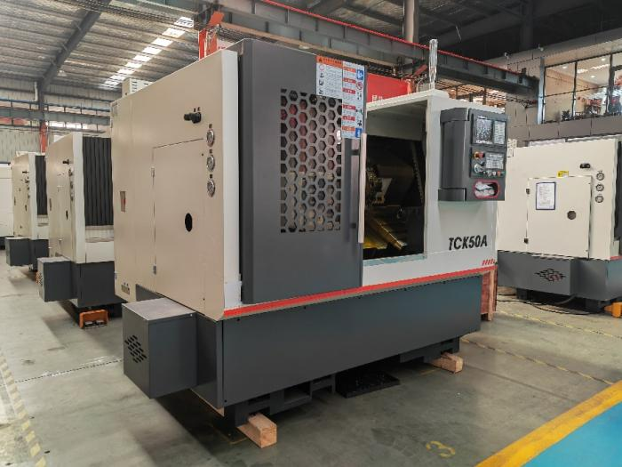
Manufacturing high-precision motor shafts efficiently requires the right equipment, optimized machining steps, and strict quality control. In modern high-volume manufacturing, the CNC slant bed lathe (especially CNC turning-milling compound machines) has become the industry standard for producing reliable, high-performance motor shafts.
At Shanghai MFG Machinery Equipment Co., Ltd, we specialize in providing advanced CNC machining solutions. In this guide, we break down the complete manufacturing process, equipment selection, tooling configuration, and essential technical tips for machining motor shafts using automated slant bed lathes.
|
 |
|---|
Key Characteristics of Motor Shafts & Material Selection
Motor shafts are vital components used across industrial and consumer applications. Understanding their typical features helps engineers optimize tool paths and machining strategies.
Typical Features: Long stepped shafts, outer diameter steps, undercut grooves, bearing journals, threads, keyways (requires C-axis/Y-axis turning-milling compound machines), and center holes on the end faces.
Common Materials:
45# Steel & 40Cr: Most widely used for standard and heavy-duty motor shafts.
20CrMnTi: Frequently used for small, high-stress motor shafts requiring case hardening.
Why Choose a CNC Slant Bed Lathe?
Slant bed CNC lathes offer superior chip evacuation, exceptional structural rigidity, and seamless integration with bar feeders. They are ideally suited for continuous automated production and batch manufacturing of small-to-medium motor shafts.
I. Raw Material Preparation
High-Volume Production: Round bar stock fed automatically via a bar feeder (typically ϕ5 to ϕ60).
Large Diameter / Short Parts: Forged blanks held securely via hydraulic chucks.
Machining Allowance: Leave a single-side finish allowance of 0.2 to 0.5 mm. For quenched and tempered materials, thermal treatment deformation must be factored into the allowance.
II. Equipment Solutions: Standard Slant Bed vs. Turning-Milling Compound
Choosing the right machine configuration impacts your cycle times, accuracy, and secondary operations:
| Equipment Type | Capabilities | Key Advantage / Disadvantage |
|---|---|---|
| Standard Slant Bed Lathe (No C-axis) | Turning, facing, grooving, threading only | Cost-effective for pure turning; requires secondary milling for keyways and flats. |
| CNC Turning-Milling Compound Lathe (C-axis + Live Tooling, Optional Y-axis) | One-champing turning + end drilling + radial holes + keyway milling | Top Choice: Eliminates secondary setups, improves concentricity, and saves overall production time. |
III. Standard Machining Workflow (Automated Bar Feeding)
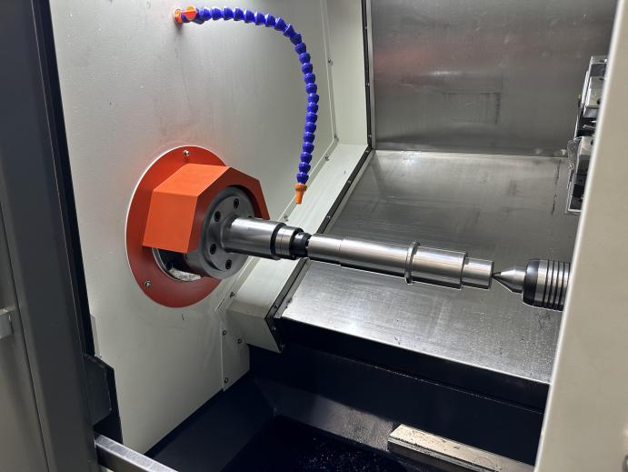
Prerequisite: Bar stock passes through the main spindle, clamped by a hydraulic chuck. A tailstock live center is utilized for long shafts to eliminate vibration.
1:Face & Center Drilling (Essential for Long Shafts):
- Tools: Facing tool, center drill.
- Purpose: Establishes the length datum and provides a center hole support for slender outer diameters to prevent chatter.
2:Rough Turning Step Diameters:
- Tools: Rough turning insert, leaving 0.2–0.4 mm finish allowance.
- Process: Sequentially machine bearing seats, rotor fit sections, and fan mounting steps. Slant bed rigidity allows high cutting speeds.
3:Machining Undercuts and Seal Grooves:
- Tools: Narrow grooving tool.
- Process: Accurately control groove width, root diameter, and chamfers in front of bearing seats and threads.
4:Finish Turning All Diameters, Tapers, and Chamfers:
- Tools: High-precision finishing tool.
- Process: Ensures precise dimensional tolerances and surface finishes (bearing journals often require Ra1.6 or 0.8). Pre-reserves grinding allowances if cylindrical grinding follows.
5:Threading (Output End):
- Tools: 60 °external threading insert using threading canned cycles.
6:✅ [Compound Lathes Only] C-Axis & Live Tooling Milling:
- Process: Locks the spindle angle to mill keyways and flat surfaces in a single setup, guaranteeing high positional accuracy.
7:Part Cut-Off:
- Tools: Parting-off tool to slice the finished part to overall length.
💡 Pro Tip for Slender Shafts: For high length-to-diameter ratios, the tailstock center must remain engaged throughout rough and finish turning to suppress deflection and chatter marks.
IV. Turret Tooling Configuration
Optimizing your tool setup minimizes downtime and maximizes surface finish quality:
- Rough External Turning Tool: Rhombic negative-angle insert for high impact resistance.
- Finish External Turning Tool: High-gloss wiper insert to ensure superior bearing journal smoothness.
- Grooving Tool: Narrow-blade grooving tool for undercuts and snap-ring grooves.
- Threading Tool: 60 ° external threading insert.
- Drilling / Center Tools: Live-tooling compatible center drills and twist drills.
- Live Milling Cutters: End mills for keyway machining (on compound lathes).
V. Critical Process & Quality Control Points
1. Concentricity Control
Motor shafts feature multiple coaxial diameters (especially bearing journals). Whenever possible, complete all turning operations in a single chucking. If the shaft is too long and requires flipping, always locate using the center hole and re-machine soft jaws.
2. Slender Shaft Vibration Control
- If the length-to-diameter ratio exceeds 10, use a tailstock center.
- Reduce depth of cut and feed rates while maintaining sharp tool geometry.
- Utilize steady rests if chatter persists.
3. Heat Treatment Integration
- Option A: Rough turn → Quench & Temper → Finish turn / Grind (Most common; requires accounting for hardness increases).
- Option B: Complete machining → Surface Induction Hardening (for wear-resistant bearing seats), followed by cylindrical grinding correction.
4. Tolerances & Allowances
Bearing fit journals usually require h6/g6 fits, while general mounting steps require h7. Because CNC lathes cannot consistently maintain tight h6 tolerances under mass production wear, precision motor shafts typically leave a small grinding allowance for subsequent cylindrical grinding.
VI. Complete Process Flow Summary
Raw Bar Stock→Auto Feeder→Clamp→Face & Center Drill→Rough Turn Steps→Groove→Finish Turn→Thread→(C-Axis Milling)→Cut-Off
VII. Application Suitability
✅ Best Suited For: Small-to-medium diameter motor shafts, high-volume automated manufacturing, 45#, 40Cr, and stainless steel materials.
❌ Not Recommended For: Extra-large, extra-long heavy-duty motor shafts (which require heavy flat-bed lathes and dedicated grinding machines). Furthermore, extremely long keyways are often more efficiently processed on dedicated milling machines rather than via turning-milling compound lathes.
At Shanghai MFG Machinery Equipment Co., Ltd, we specialize in high-performance industrial machinery and export solutions for global manufacturing operations. Whether you are looking for cnc lathe for motor shafts , or heavy-duty metalworking equipment, our engineering team is ready to help.
- Website: https://www.mfg-machinery.com/
- Email: info@mfg-machinery.com
- Phone: 008615803802793
- Address: No. 408 South Yunzao Road, Baoshan District, Shanghai, China