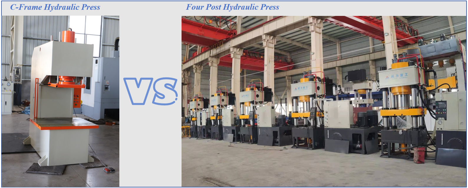
Choose a C-frame hydraulic press when the line needs open access from three sides, robot loading, quick die changes or frequent operator work.
Choose a 4-post hydraulic press when the job uses a large die, needs stronger platen guidance or applies high force across a wide working area.
Do not size the press from expected force alone. A process requiring 48 tons should not run on a 50-ton press all day. Leave capacity for material variation, friction, tool wear and pressure spikes. Also check cycle rate, holding time, off-center load, daylight and stroke.
Start With the Way Parts Enter the Press
The frame choice often becomes clear when you follow the part through the line.
Can a robot enter from the side? Does the operator change tooling several times per shift? Will a conveyor pass through the working area? If so, the open front and sides of a C-frame press make loading easier.
Now look at the tool. Is it wide and heavy? Does the operation place force away from the center? Must the moving platen stay parallel throughout the stroke? These conditions may point toward a 4-post press.
The right frame is the one that supports the real loading method and force path.
C-Frame or 4-Post: Quick Comparison
| Selection point | C-frame press | 4-post press |
|---|---|---|
| Work access | Open on three sides | Posts limit side access |
| Robot loading | Easier to arrange | Must clear the posts |
| Quick die change | Good side access | Removal path needs planning |
| Large tooling | Limited by throat size | Better for wide platens |
| Off-center load | More sensitive | Better guided, but still limited |
| Line integration | Easy for feeders | Best for centered operations |
| Floor space | Often more compact | Usually needs more space |
| Common work | Assembly and punching | Forming and large-part pressing |
A 4-post machine does not make every load safe. The work should still be placed near the press center. Always confirm the permitted off-center load with the supplier.
Where the C-Frame Saves Time
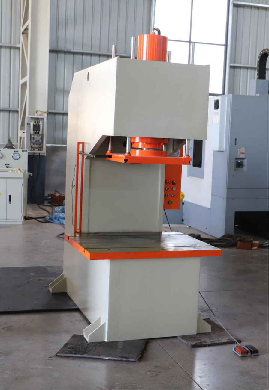
A C-frame press gives the robot, operator and maintenance team a clear path to the die area. Parts can enter from the front or side without passing between four columns.
This is useful for automated assembly, bearing insertion, bushing pressing, light punching and straightening. It also helps with quick die change (QDC) because clamps, die lifters and rolling bolsters are easier to reach.
The trade-off is the open frame. Heavy or off-center force can cause the throat to open slightly under load. This elastic movement may affect tool alignment and part accuracy.
Buyers planning an automated workstation can compare throat depth, table size, stroke and loading access in the MFG Machinery C-frame hydraulic press range.
Where Four Posts Add Stability
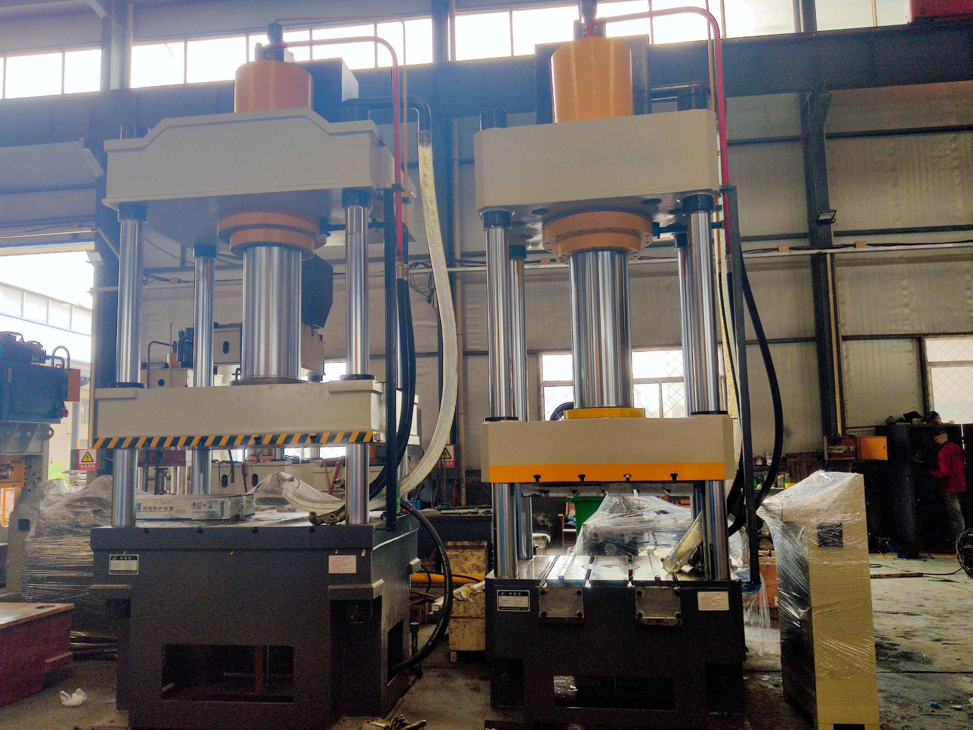
A 4-post press guides the moving platen along four columns. This layout works well with wide tools and centered loads that must remain aligned through a long stroke.
Common applications include compression molding, deep drawing, large-part assembly and forming across a broad surface.
The posts take up space around the tool, so robot reach and die-change direction must be checked before ordering. A press can have enough force but still create a line problem if the gripper, part or die cannot pass between the columns.
How Much Press Tonnage Do You Need?
Different processes require different calculations.
Punching and Blanking
Use the cut perimeter, material thickness and material shear strength.
Required force (kN)
= Cut perimeter (mm) × Thickness (mm) × Shear strength (N/mm²) ÷ 1,000
Convert the result to metric tons-force:
Required tonnage (metric tons-force)
= Force (kN) ÷ 9.81
For example, consider a 100 mm cutting perimeter through 5 mm steel with a shear strength of 300 N/mm²:
100 × 5 × 300 ÷ 1,000 = 150 kN
150 ÷ 9.81 ≈ 15.3 metric tons-force
This result covers the cutting force only. Stripping force, tool condition and process variation must also be considered.
Press-Fit Assembly
A basic estimate for inserting a round part is:
Press-fit force
= Contact pressure × Contact area × Friction factor
For a cylindrical fit:
Contact area
= π × Diameter × Engagement length
Contact pressure depends on interference, material stiffness, wall thickness and part shape. Because these values are not always known, use engineering fit data or record the peak force from a proven test.
For critical assembly, use a load cell and record the full force-position curve. A final pressure reading alone may not reveal a tilted or damaged part.
Why a 50-Ton Press Is Wrong for a Repeated 48-Ton Job
A 50-ton rating is the maximum available force. It is not a good target for every production cycle.
Running close to the limit leaves little room for harder material, dry parts, tool wear or pressure spikes. The pump, seals and hydraulic oil also work under high load, especially when the process includes holding pressure.
For early sizing, a capacity margin of about 20% to 30% is common. Final selection must still follow the machine maker’s duty rating and the actual cycle.
Early sizing estimate
Selected capacity = Normal peak load × 1.20 to 1.30
For a measured 48-ton operation:
48 × 1.20 = 57.6 tons
48 × 1.30 = 62.4 tons
This process may therefore require a 63-ton or larger press, rather than a 50-ton machine. Frequent cycles or long holding times may require additional capacity or hydraulic cooling.
Fast Sizing Check
| Production problem | Likely cause | Check |
|---|---|---|
| Full pressure every cycle | Press is too small | Peak force and duty rating |
| Oil heats quickly | High load or long hold | Cycle profile and cooling |
| Parts enter at an angle | Poor guidance or fixture | Platen and tool alignment |
| C-frame opens under load | Off-center or heavy force | Load position and deflection |
| Robot cannot reach the die | Poor access planning | Gripper path and opening |
| Die change takes too long | Removal path is blocked | QDC layout and clearance |
| Parts crack at random | Force setting is not enough | Force-position curve |
Market Insight: Buyers Are Specifying the Whole Cycle
Assembly-line buyers are moving beyond requests such as “send us a 100-ton press.”
They now provide the force curve, cycle time, holding time, daily output and loading method. This helps determine whether the press can repeat the job without overheating, losing alignment or stopping the line.
Automation also changes frame selection. Open access may be more useful than extra table width when a robot loads a new part every few seconds. For a large die under high centered force, platen guidance may matter more than side access.
Send the Process Data, Not Only the Tonnage
For an initial press selection, send MFG Machinery:
- Part drawing and material
- Punching, forming or press-fit process
- Estimated or measured peak force
- Required stroke and daylight
- Table and tool dimensions
- Cycle time and holding time
- Parts required per shift
- Loading direction
- Robot or feeder layout
- Tool weight and die-change method
- Expected off-center load
A process video or force-position curve will help when available. These details allow the frame type, working capacity, cylinder size and hydraulic system to be checked against the actual production cycle.
Send the application details to info@mfg-machinery.com with the subject line:
Hydraulic Press Selection – [Process] / [Peak Force] / [Cycle Time]